Posted on Leave a comment

THE PILOT SCHOONER 40C

A Project in Search of a New Home

By Reuel B. Parker

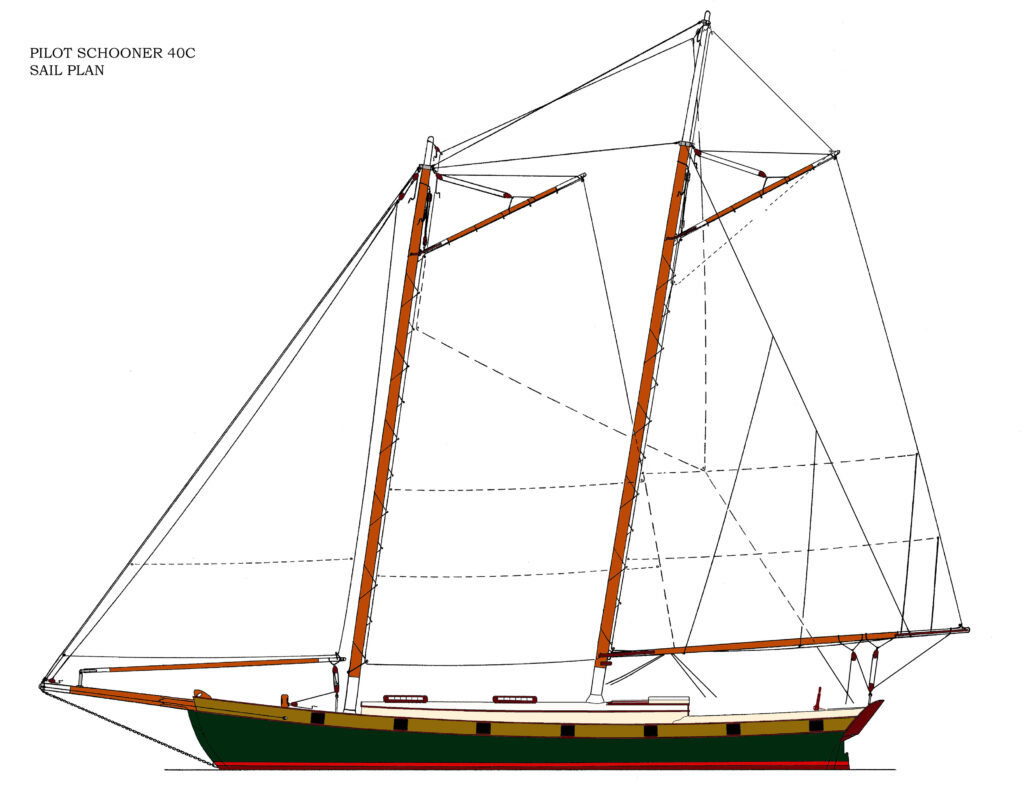
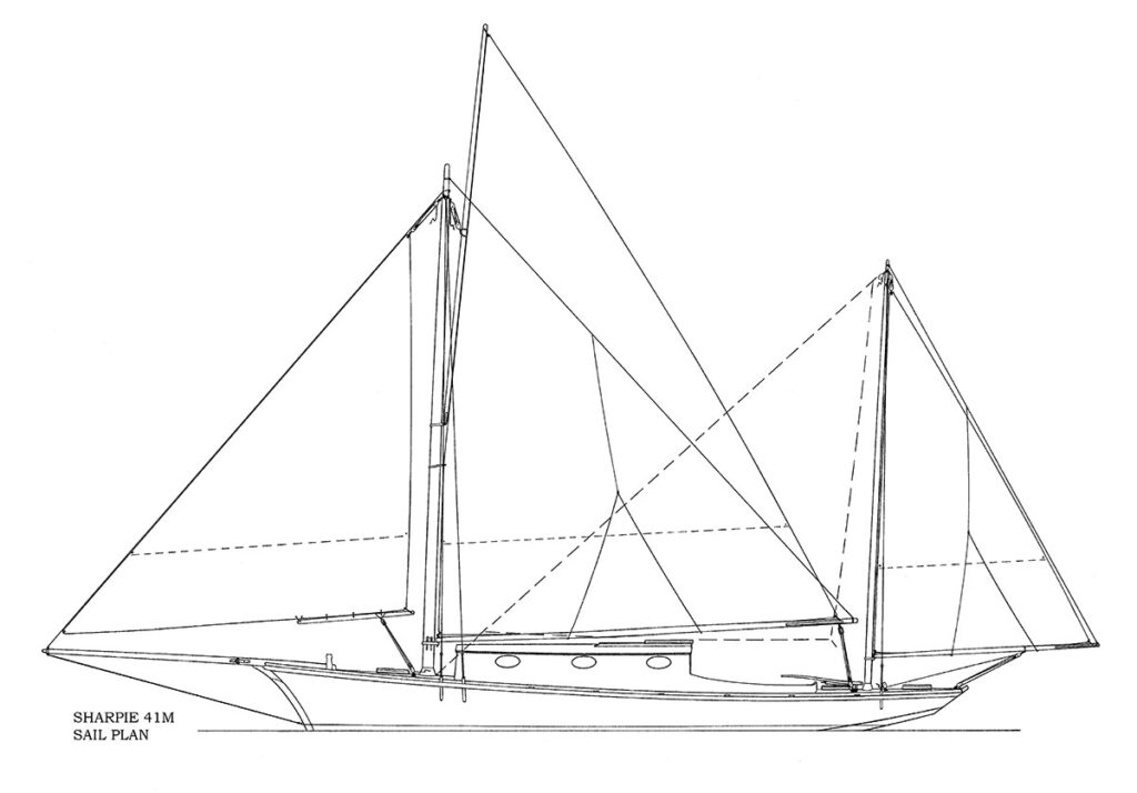
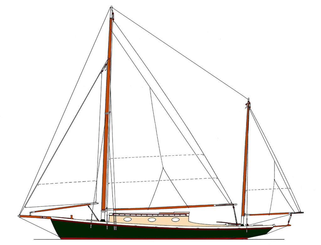
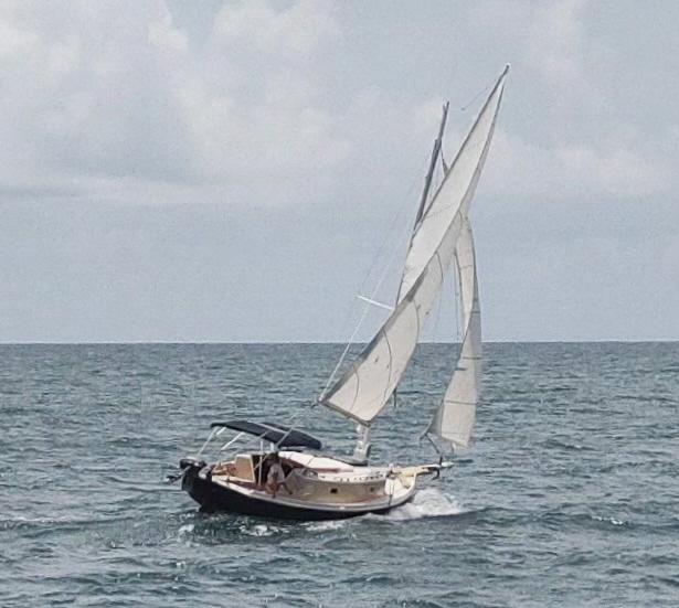
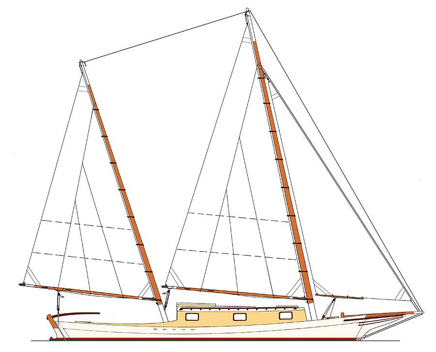
Sail Plan for the Pilot Schooner 40C

In early 2020 I met Chelsea Ragland, who was crewing for Danger Charters. My close friend Wayne Fox, who owned Danger, had put me in touch with Chelsea because she wanted to learn about boatbuilding. Danger runs three charter schooners of my design; one of which I built back in 1984 (the Exuma 52 SARAH).

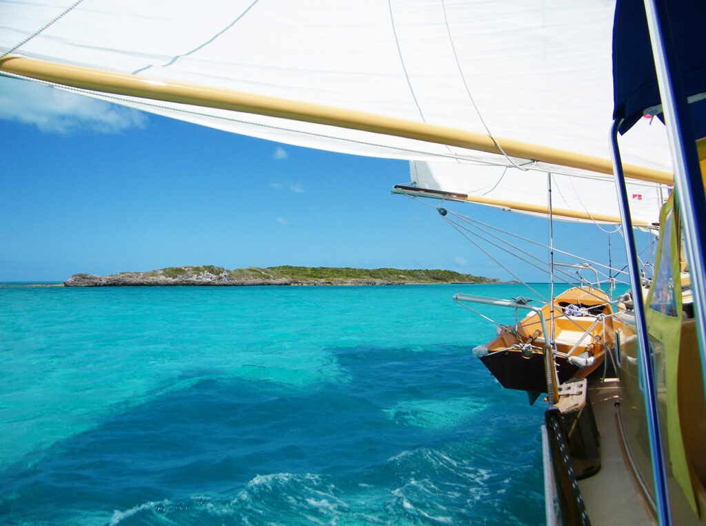
At the time I was getting ready to sail PEREGRINE, my new cold-molded centerboard ketch, on a cruise to the Bahamas. Chelsea had never been to the islands, so she signed on as crew, giving us lots of time to talk about boatbuilding while enjoying paradise. We chanced to arrive in Bimini 12 hours before the Bahamian government closed the entire country to tourism (due to the Covid 19 pandemic), which made our cruise abbreviated, though we still managed to sail to some beautiful places … especially remote ones where we would have minimal contact with the native population, avoiding the strict regulations the government put into effect.

After we returned stateside, Chelsea contacted a childhood friend from her native Texas, and proposed that she build a cruising sailboat for him, and that I design it and help make it happen. Since I live in midcoast Maine during the summer season, Chelsea and her friend came to visit me at home, where we discussed the boatbuilding project. We chose my Pilot Schooner designs as a “point of departure,” and together worked out the parameters that would satisfy our client, and implement Chelsea’s boatbuilding dream.

For the schooner’s design, I worked from my Pilot Schooner 45 plans, creating a smaller version. The vessel that emerged would be cold-molded in Port Orford cedar, supplied by Americas Woods, a distributor of boatbuilding lumber in Washington, Maine. Construction would be triple-laminated using the methods described in my first book, The New Cold-Molded Boatbuilding.

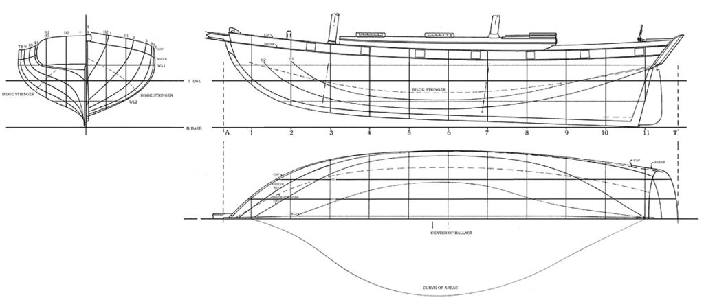
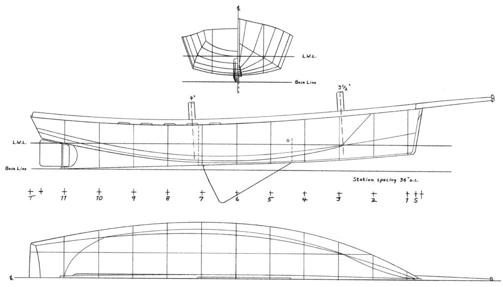
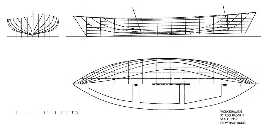
Partial Lines for the Pilot Schooner 40C

Specifications are as follows:

L.O.A.             40′

L. EXT.           54′

L.W.L.             35′ 6 1/2″

BEAM             12′

DRAFT            4′ 2”

DISPL.             27,500 lbs. (13 U.S. tons) Laden

BALLAST         9,500 lbs. Lead (3,750 lbs outside; 5,000 lbs inside; remainder in tankage and trim)

SAIL AREA       914 sq ft working/1,254 sq ft total (light air)

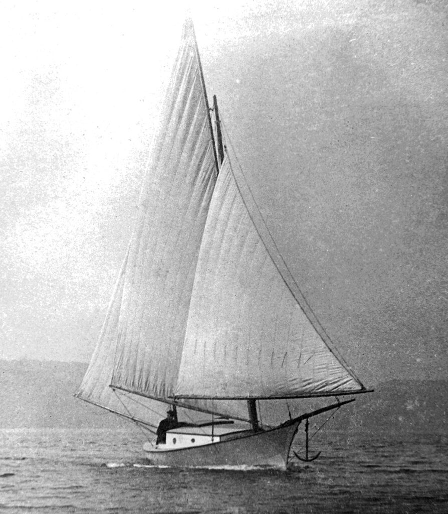
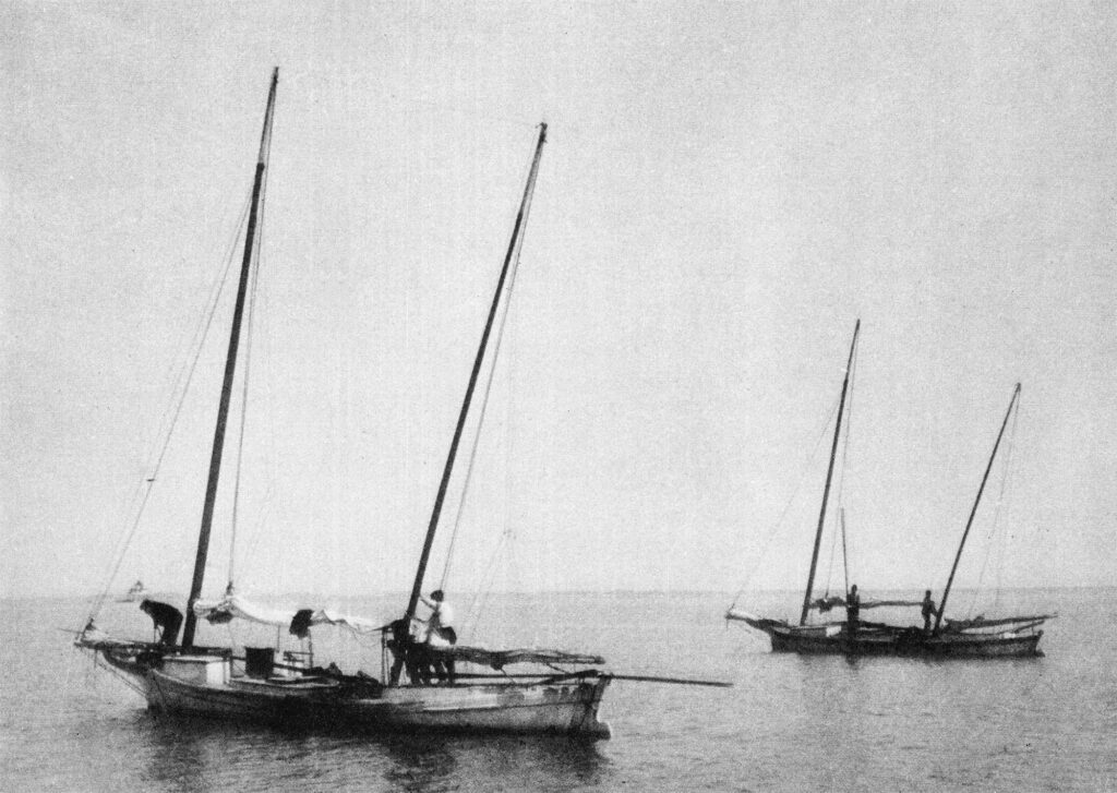
TYPE                Full-keel pilot schooner yacht based on early 19th-century

Virginia models (Baltimore Clippers). Hull Speed: 8 knots

POWER            Inboard diesel, 40 to 60 H.P., under cockpit well

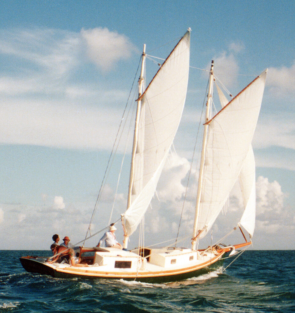
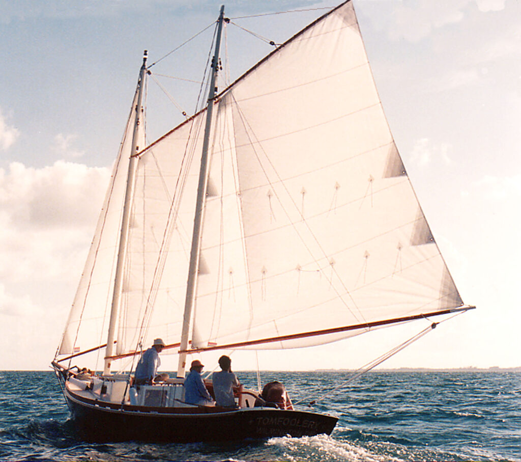
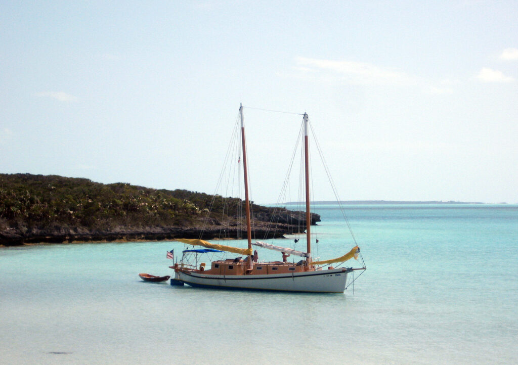
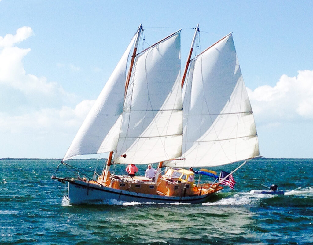
RIG                  Free-standing gaff rigged schooner with overlapping fores’l, self-tending jib and light air fisherman tops’l. The jib may be set flying with luff tension provided by a downhaul; or may use roller furling. The traditional jib is lowered by luffing up, releasing the halyard and tack downhaul, and stuffing the sail and club-foot into the fore-hatch. The roller furling jib may have doubled sheets or may be sheeted to the boom shown. The mains’l clew may be seized to a ring which slides forward when the outhaul is slacked, bringing the mains’l on deck OR may be reefed/furled to the boom if full-length battens are employed (suggested). This rig is one of the simplest ever conceived; yet it has power, versatility, practicality and economy. Howard Chapelle felt it should be revived for use in cruising yachts because of these qualities, without modification. So do I!

ACCOMMODATIONS      Interiors (2) shown sleep five. Double cabin aft. Head/shower forward. This is a comfortable, practical vessel, capable of extended ocean cruising anywhere in the world. Water capacity is 100 gal or more with a second tank under the hold. Fuel capacity is 200 gallons or 300 gallons (Alt. Plan).

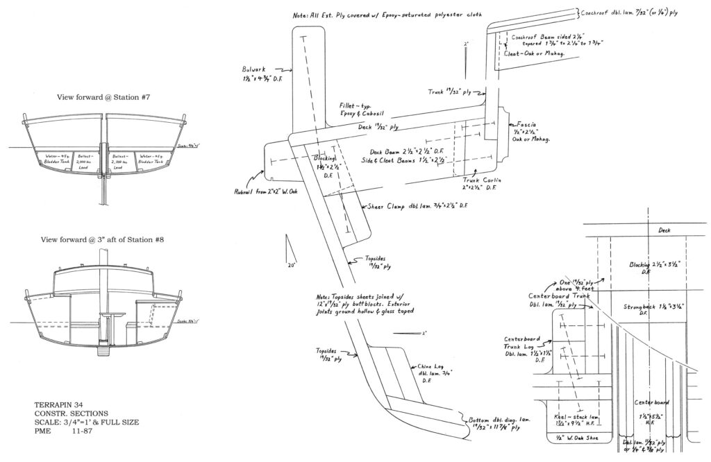
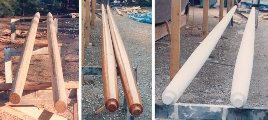
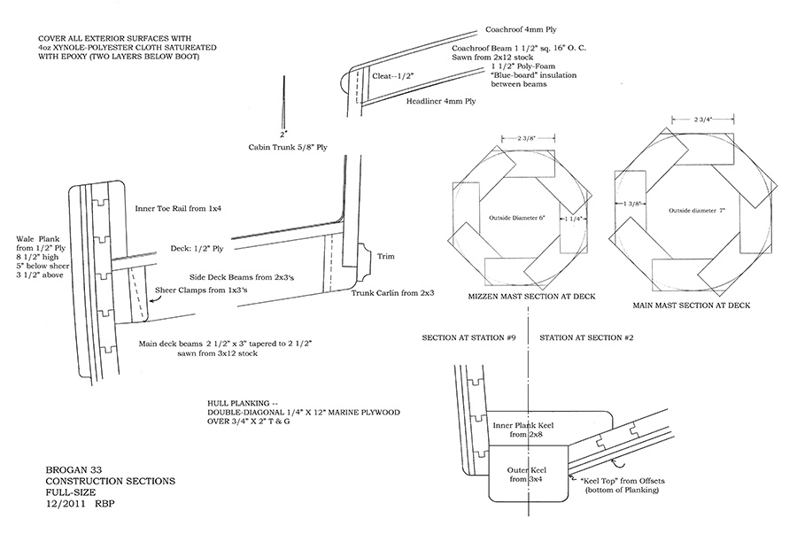
CONSTRUCTION       Cold-molded wood/epoxy/fabric: Hull — double diagonal 5/16″

marine ply or solid planks over 3/4″ tongue and groove lumber. Outside Xynole-polyester covered; two layers below boot top. Decks – 1/2″ ply over sawn beams, Xynole-polyester covered.  Coachroofs — 3/8″ ply. Masts are hollow octagonal free-standing Douglas fir, booms and gaffs are solid Douglas fir.  Interior — painted plywood trimmed with varnished hardwoods.

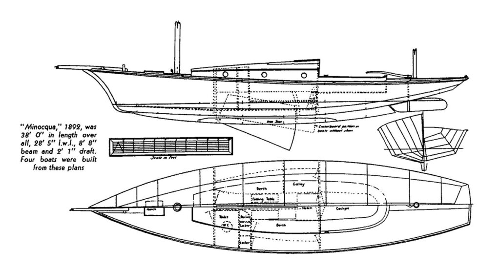
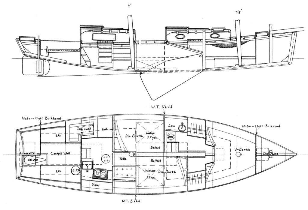
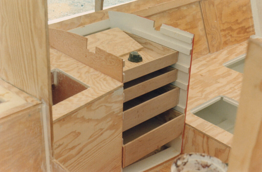
I designed an interior plan based on our client’s parameters, but later changed it to the more traditional arrangement shown here:

Plan & Inboard Profile for the Pilot Schooner 40C

I elected to divide the ballast between a steel box keel filled with fitted blocks of solid lead, and inside ballast placed on the keel below the cabin sole. With a ballast ratio of 34%, this will be a very stiff hull, with righting moments beyond full capsize. But with moderate draft (4’ 2”), and ballast relatively high (compared to modern yachts), the motion of this schooner will be much gentler than for most yachts. Strongly raked, free standing masts of moderate height also indicate gentle motion.

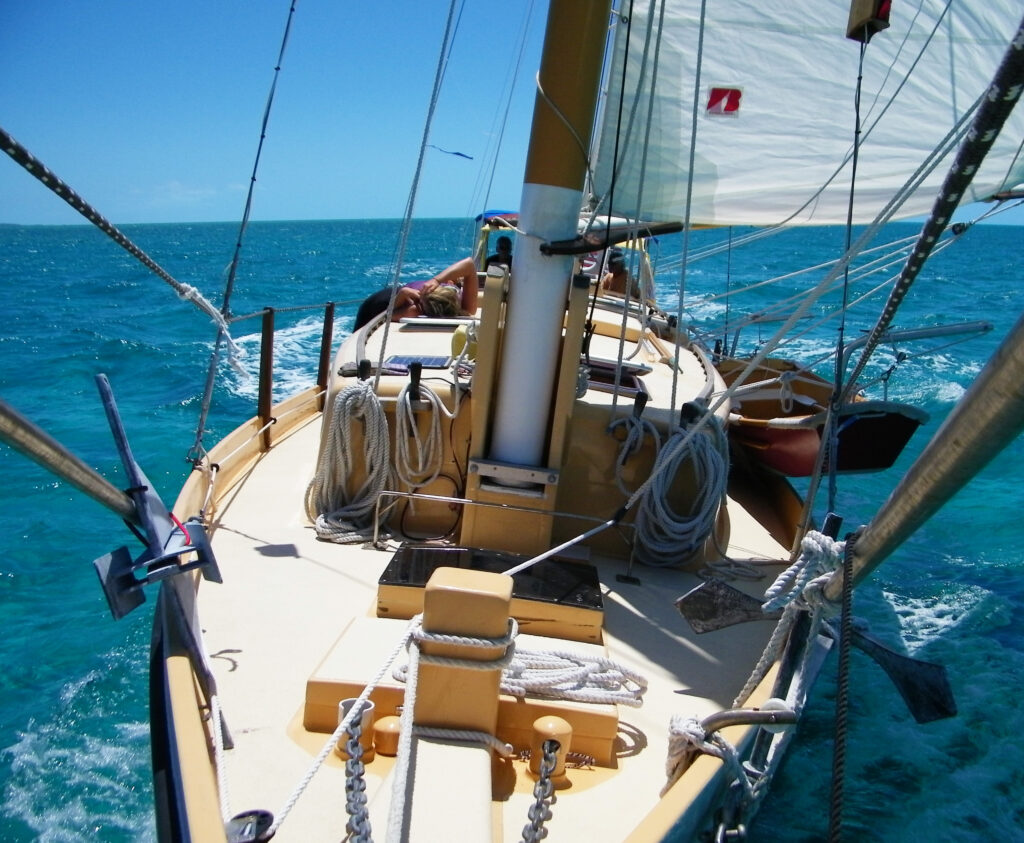
Accommodation is for four people, with a large settee available for a fifth. The design also includes a cargo hold/food pantry with a second large optional integral water tank below it. The schooner will carry enough water, stores and fuel for long-range cruising. She will not be fast (hull speed is 8 knots), but she will be powerful, comfortable, and eminently seaworthy. She can go anywhere. She will stand up under her canvas, and carry it longer than most yachts. And the schooner rig has more options for carrying additional sail than any other rig. A little-known feature of free-standing masts is that by letting the sails out just forward of the beam, the vessel will steer herself downwind. And with the helm lashed on a beat, she will steer herself upwind. And the reef points will have full-length battens immediately above them.

Construction Sections for the Pilot Schooner 40

Whereas I often specify marine plywood for the diagonal planking, for this build we opted to use solid Port Orford cedar milled to 5/16’ X 5 3/8” planks – a convenient size for diagonal planking a very “curvy” hullform – also convenient to mill from Americas Woods’ available stock. The hull would employ solid Douglas fir and pressure-treated pine for the backbone – inner keel, apron, horn timber, knees, etc. Bulkheads would be 5/8” marine plywood, some of which were conveniently located at design stations. Remaining design stations were made from mold frames in the conventional manner.

I introduced Chelsea and our client to my friends at Hylan and Brown Boatbuilding, and we arranged for workspace in their yard, including help from one of their professional boatbuilders, and use of their large bench tools.

In July of 2020, construction got started, materials were ordered (epoxy and related products were shipped from Florida), and summer was in full bloom. Chelsea and I lofted the schooner’s design stations on two sheets of MDO plywood, the Strong Back was laid, bulkheads cut out, and design-station frames built. The frame was erected on the strong back, and with backbone, sheer clamps and bilge stringers, the hull began to take shape. I worked hands-on in the beginning, then shifted to advisory status as the work progressed. Finally, Chelsea kicked me out because I was old and in the way!

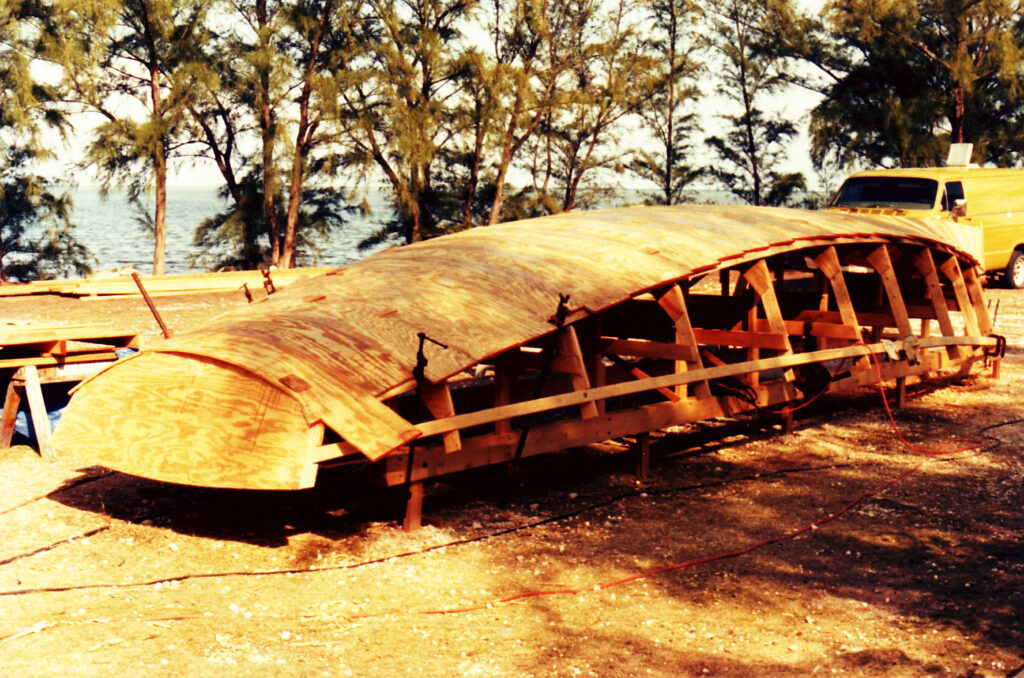
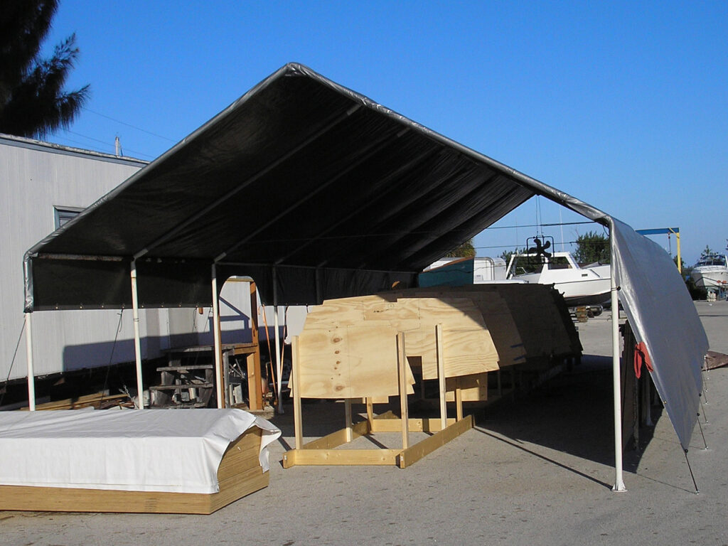
The Pilot Schooner 40C hull in frame

By early Fall, the bare hull was planked, without stem, outer keel, or sternpost. At that point, with cold weather rapidly encroaching, Chelsea had to decide whether to store the hull in a friend’s barn for the winter, or have it shipped to my shop in Florida, where she could continue working on it. She decided on the latter, which would include hiring my late partner Bill Smith to help her, fabricating all metal parts including a steel box keel for outside ballast, help with cabinetry, systems, etc. I would help part time with spar-making, rigging, machinery, and systems also.

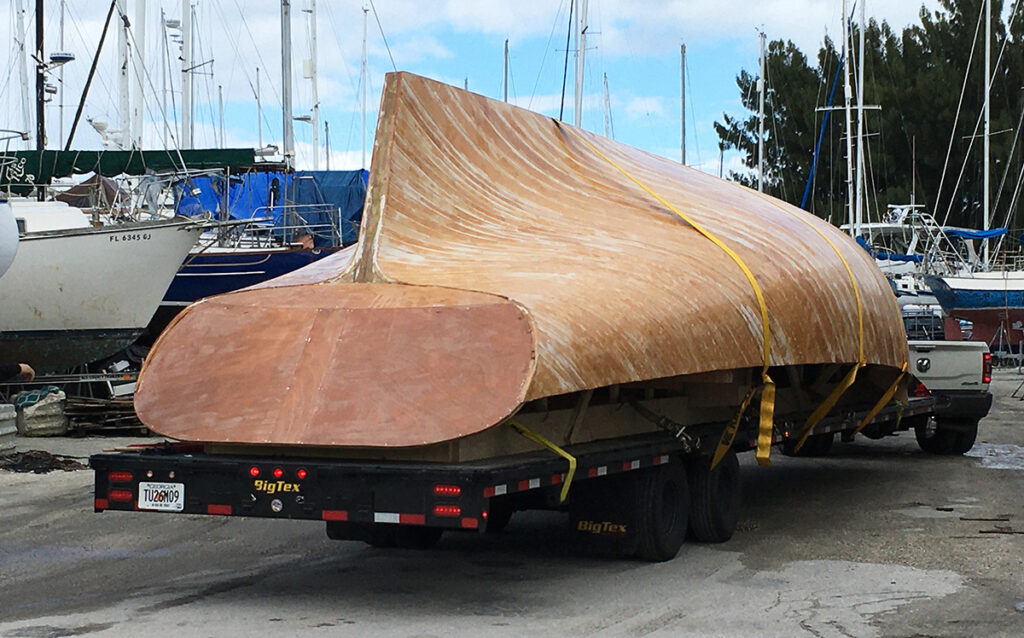
The bare schooner hull arriving at my shop in Riverside Marina, Florida

When the hull arrived in Florida, we unloaded it, plus various remaining supplies. We blocked the hull upside down in my work space, and began organizing our seasonal work plan. Chelsea arrived soon after. And at that point, our client pulled the plug on the project, for reasons that were never explained, and left the three of us without work. This destroyed the very tight schedule that would be required to accomplish our goals through the winter work season. All three of us had arranged our lives around this project, and suddenly we were left swinging in the breeze. This was particularly devastating for Bill, who had cancelled other work projects for this one, and was left suddenly unemployed.

Many weeks went by, with Chelsea trying to get the project back on track. In the end, our client – really Chelsea’s client – made a number of severe and vulgar accusations against Chelsea, causing her severe stress and unhappiness, and completely terminating the project. He abandoned the whole thing, leaving the hull stranded in my work space. He declined to pay rent on the space, refused to reclaim his property (we were all owed money), and terminated all communication.

Eventually we had the hull moved to my friend David Halladay’s “Boatsmith” facility in Jupiter, Florida. My late partner, Bill Smith, had made the steel box that would contain outside ballast, which was also moved to Boatsmith.

At the time of this writing, in early February of 2024, the hull is likely to be moved again, this time to a friend’s storage facility in Tampa, Florida.

The purpose of this article is to offer this project to someone who has the resources, abilities, and drive to complete it. I am offering the bare hull, with the box keel, for sale for $10,000. The package includes a full set of plans for the project.

Posted on Leave a comment

THOMAS CLAPHAM AND THE ROSLYN YAWL

By Reuel B Parker

The Roslyn Yawl MINOCQUA under sail in the 1890s—note the “balance jib”

(photo courtesy of Gordon E. Hurley, Jr.)

In the late 19th century, the sharpie type of inshore fishing boat began to insinuate itself into the world of yachting. In addition to the obvious qualities of speed and shoal draft, the low cost and simplicity of sharpies encouraged a new breed of yachtsman, who previously had not been able to afford anything that might be called a “yacht”. 

As sharpies evolved into yachts, various modifications of hull and rig were employed that might have been considered “improvements” over the original fishing, oystering and crabbing models. A number of innovative designers and builders got into the act, and some remarkable vessels resulted.

One of these men was Thomas Clapham, from Roslyn, Long Island, New York. While the true sharpie hull is flat-bottomed, Clapham created a hull with moderate, fairly constant deadrise from amidships aft, and with increasing deadrise from amidships forward. While these modifications created a whole new animal in marine architecture (the V-bottom boat), Clapham called his invention a “Non-Pareil Sharpie”.

MINOCQUA’s Lines, from The Sharpie Book (originals traced from Clapham by Howard Chapelle)—note the optional outside-ballast keel

Another innovation employed by Clapham was the addition of an optional full-length, curved keel, which incorporated outside ballast, making the design truly ocean-worthy. In general proportions, however, the new design was consistent with true sharpies in beam-to-length ratio, extreme shoal draft, low freeboard and strongly flared topsides.

Both bottom and topsides planking employed “developable surfaces” (able to be planked from flat panels), allowing planking from standard lumberyard plank stock with no spiling required. In this, Clapham’s hull retained the simplicity of construction and low cost of the true sharpie.

What this means in today’s world of cold-molded wood/epoxy construction is that the hull can be built easily, rapidly, and very inexpensively using full sheets of marine plywood. It can also be easily built in aluminum or steel.

I included MINOCQUA in The Sharpie Book (1994), but didn’t draw building plans for her until a decade later (2004), when I designed my own version for cruising, which I named MINOCQUA II. I designed my version to be built using full sheets of marine plywood over longitudinals and plywood bulkheads. In 2007 I designed a slightly larger model (41 feet) to achieve standing headroom in the cabin. I added a skeg-type hollow box keel, incorporating lead ballast, to make my model self-righting from a full-knockdown (capsize to 95 degrees).

Plan and Inboard-Profile views of my 41’ cruising version of MINOCQUA II

Clapham’s rig is unusual by today’s standards, employing a long, sprung-down plank bowsprit with a big self-tending jib, a “Sliding-Gunter” mains’l, and a yawl Marconi mizzen. I would, however, make one concession to modern thinking, by employing a roller-furling system for the jib.

The famous Roslyn Yawl sail plan, on my 41’ cruising version of MINOCQUA II

Proportions for MINOCQUA II are:

L.O.A.                     40’ 10”

L.W.L.                     31’ 7”

BEAM                     10’ 0”

DRAFT                   2’ 2”

DISPLACEMENT    8,750 lbs. (approx.)

BALLAST                3,250 lbs. (approx.)

SAIL AREA             750 sq. ft.

TANKAGE              Fuel: 55 gal. Water: 110 gal.

AUXILIARY POWER Inboard 2-cyl diesel (15hp) or outboard in an offset well located just aft of station #6

My modernized Sail Plan for MINOCQUA II

Thomas Clapham was an outspoken champion of shoal-draft yawl-rigged cruisers, and designed numerous additional models, including a 61’er for a member of the New York Yacht Club in 1881. His nonpareil sharpies could be single-handed by lowering the main in strong winds and sailing under “jib and jigger”. His designs had a great reputation for speed, and won many races. They were well-balanced, often steered themselves, and sailed with dry decks in rough weather. His hulls were remarkably stable, and were considered uncapsizable with the optional outside-ballast keels.

In the November 1915 issue of Yachting, William J. Starr wrote:

…flaring topsides and lifting type of overhanging ends gave them much reserve buoyancy and stability in spite of their relatively narrow breadth.… In form of section these Clapham sharpies were the V-bottom boats of today—nothing more, nothing less—starting with a sharp V entrance forward (originally used to prevent pounding), with a good amount of straight deadrise amidships, and flattening somewhat aft into a very clean run. The secret of their speed with small driving power and their clean sailing was the perfectly fair segmental rockering of their bottoms from forward to aft, and perhaps fully as important, the perfect diagonal formed by the sweep of their bilge when heeled under sail.

What this technical description means to the layman is that water flowing under this hull, when heeled over, has the minimum possible impediment, and that the immersed planes of hull bottom and topsides are symmetrical, with the chine acting like second keel. Starr further explains that Clapham experimented with towing models, and faired his lines using straight-grained pine battens, to assure that there would be “no concealed humps or hollows to stop the clean run of the water.” Brilliant architecture!

I think Thomas Clapham, right along with Nathanial Greene Herreshoff and Ralph Munroe, must share the title of “Father of the Modern American yacht”.

Appleton, Maine, 10/21/13 (Originally Blog #4 for WoodenBoat online)

Posted on Leave a comment

THE QUICK-MOLDED TERRAPINS

REVIVING A CLASSIC

THE TERRAPIN SERIES

BY Reuel B. Parker

The Terrapin 34 TOMFOOLERY under sail in the Florida Keys

A long time ago, I came across a pair of marvelous books on wooden boatbuilding by Harry Sucher: Simplified Boatbuilding—The Flat-Bottom Boat, and Simplified Boatbuilding—The V-bottom Boat. Both were published in 1973 by W.W. Norton & Co. I still cherish my well-worn first-edition copies. Browsing through the second book I came across a “33’ Modified Sharpie Terrapin Schooner” on pages 283, 284 & 285. Sucher’s plan shows a flat-bottomed hull with increasing deadrise in the quarters to the transom. The little schooner has low-freeboard, twin houses (very low), and a self-tending gaff schooner rig. The bottom is cross-planked forward, and file-planked aft, in the deadrise part of the hull. Sucher claims that his design is based on “terrapin schooners” from the 1880’s that were used in the turtle fisheries in Florida and the Gulf of Mexico. I believed him, of course, and for many years I thought that’s where they originated.

Two decades or so later, when I started my research for The Sharpie Book, I turned up information (and a sketch) in Howard I. Chapelle’s The National Watercraft Collection (U.S. National Museum Bulletin 219; 1960), garnered in turn from Small Yachts: Their Design and Construction, Exemplified by the Ruling Types of Modern Practice by C.P. Kunhardt (1886). It turns out that the terrapin schooners were actually sharpie fishing smacks used on the Chesapeake Bay and waters southward.

Kunhardt’s drawing of a terrapin smack, from Forest and Stream, 1885

What defines a “smack” is a wet fish hold, created by isolating the large middle portion of a vessel’s hull with watertight bulkheads, and drilling small holes in the bottom to flood the hold. Fish in the hold will thereby have a healthy environment to thrive in until they can be taken to market. No ice required. This would work well for keeping turtles also, but I have never found a reference (other than Sucher’s) that the smacks were so used. It seems plausible that they were, even though they were certainly inshore fishermen. I can envision them sailing along the Southeast Florida coast, harvesting turtles swimming off the beach after laying their eggs.

Chapelle also described the terrapin smacks, in more detail, in Paper 25: The Migrations of an American Boat Type (1961—Library of Congress), including a Lines Drawing.

Chapelle’s lines drawing of a Maryland Terrapin Smack, based on a wreck, sketches, photographs, and dimensions given by Kunhardt— from Paper 25 (Library of Congress)

The dimensions of Chapelle’s terrapin smack are 37’ 10 ½” between perpendiculars, 9’ beam, and 1’ 7 ¼” draft. The wet well is divided in half by the centerboard trunk.

It is of note that Chapelle’s drawing has no deadrise aft, which made me speculate that Sucher may have added it of his own volition (a common modification), except that if you look closely at Kunhardt’s sketch, you can just see deadrise at the transom. It is also of note that a similar type existed on the Chesapeake Bay, which did have a flat bottom forward with deadrise aft, and was known as the Hampton Flattie. These varied in size from 16’ to 30’, according to Kunhardt, who wrote about them also for Forest and Stream. The “flattie” models were smaller than the “terrapin” models, and were rigged as gaff sloops. Chapelle found a hulk near Elliot, Maryland, about 1940, and drew plans based on it. The flatties were used for oystering and crabbing, while the terrapins seem to have all been fishermen (smacks). (I sell plans for a 24-foot “flattie” sharpie.)

In the mid-1980’s, two friends approached me with a request for an extreme shoal-draft, low-cost, charter bareboat for the Indian River area of Florida’s east coast. I designed my own Terrapin Schooner in response. My first hull lines were for an arc-bottom modified sharpie 34’ between perpendiculars, 10’ beam and 2’ 3” draft. I later designed a second version (of the same dimensions) with deadrise forward (V bow sections), which I felt would be more seaworthy, and which would not pound (the nemesis of sharpie hulls).

The Lines for my deadrise (arc-bottom) Terrapin 34 design

I designed my terrapin to be a simple cruising sailboat, with the hope that several would be built and rented as “bare boats” out of Ft. Pierce, on the Indian River. I should mention here that the Indian River is a long, narrow, shallow estuarine lagoon, protected by barrier islands, teeming with wildlife of great diversity. There is excellent fishing and collecting of clams and oysters in season. There are many endangered manatees. The bird life alone is fantastic. Wildlife enthusiasts could easily spend a week cruising the Indian River from Stuart to Cape Canaveral, stopping to anchor each night in protected coves. There are numerous parks and wildlife refuges right on the water. My terrapin would be equally at home in Florida Bay, the Keys, the Bahamas, and cruising the coasts of the southeastern United States. She would also be an excellent choice for Mississippi, Georgia, the Carolinas, Chesapeake Bay, and the shallow inland waters of New Jersey.

Plan & inboard profile for the Terrapin 34 cruiser

Unfortunately, the bareboat enterprise never materialized (I still believe it was a great idea), and I relegated my design to the status of “stock plan.” But in 1989 I received a phone call from a retired colonel in Texas, who said he was driving to my Islamorada boatyard (in the Florida Keys) to meet me. I tried to discourage him, until he mentioned that he was bringing money!

Even though it was very late in our “building season” (neither I nor epoxy can tolerate the Florida heat between May and November), we started construction on the first Terrapin 34 schooner in April of 1989, and launched the finished TOMFOOLERY sixteen weeks later that July.

The first Terrapin 34 in frame, Islamorada, Florida, 1989—note the refrigerator (upper left corner) required for controlling epoxy curing times in high heat conditions

During the design process for the Terrapin 34 I had chosen a simplified version of my usual method for cold-molded hull construction, which I dubbed “quick-molding.” This involved double-diagonal planking the hull bottom using the thickest plywood planking that could take the curves involved, and full-sheet 5/8” (actually 19/32”) plywood for the topsides planking, joined by butt-blocks. For the first Terrapin hull I specified 5/8” BBOES plywood, used in forming concrete. This yellow pine plywood seemed to be of very good quality, with almost no core-laps or voids, thick surface veneers, and very few “footballs” (knot-plugs). The slightly oily surfaces bonded thoroughly to epoxy during my tests, and I really thought I was on to something! (I am always searching for good, cheap plywood….)

Construction Sections for the Terrapin 34

Construction went rapidly and well, with a crew of six. I divided my work force into two and sometimes three crews, each with separate projects. Thus we were simultaneously building the hull, centerboard and rudder, spars, and making custom stainless-steel hardware.

Diagonal Planking—first layer

The hull went together easily and quickly, although we broke a couple of planks on the curvaceous stern. Decks consisted of the same 5/8” plywood, laid over sawn Douglas fir beams.

Solid Douglas fir deckbeams and carlins being installed—note the solid blocking used between the beam-ends on the shelves

Masts were got out of solid full-dimension 6×6 air-dried Douglas fir timbers, and booms and gaffs from smaller fir timbers.

Masts came from fir timbers, laid out square, tapered, and octagonal

The masts were then power-planed, sanded, epoxy sealed, primed, and painted

The interior consisted of painted plywood trimmed with varnished mahogany—simple but elegant. The colonel specified that no thru-hulls be installed, so I gave him a removable basin whose contents he could toss overboard. The head consisted of a similar arrangement. There was also a large ice hold, and a two-burner stove. Total materials costs, including outboard motor, sails, upholstery and rigging, were $24,000. Labor was about twice that figure.

The plywood interior being roughed in – Icebox, Galley Drawers, Double Berth

Power consisted of a 4-stroke Yamaha 9.9hp outboard located in a well in the cockpit. Sails and running rigging were Dacron; anchor rodes and dock lines were Nylon (I spliced the rodes to 5/16” hot-dipped galvanized chain), and standing rigging was hand-spliced 5/16” stainless-steel, with galvanized rigging screws and stainless-steel chain plates. All exterior surfaces were covered with epoxy-saturated Xynole-polyester cloth—with two layers on the bottom. All exterior paint was polyurethane over epoxy primers. Bulwarks were Douglas fir finished bright.

We launched TOMFOOLERY in July, and she was a pretty sight.

Launching TOMFOOLERY in July, 1989—the author is to the right of the centerboard

The colonel and his wife came for sail trials, and to take TOMFOOLERY home to Texas with a hired captain. The little schooner sailed fast, was stiff, balanced, pointed well, and was quick in stays—never missed a tack. I felt she motored well, but the colonel thought she should do better, and tried putting the outboard on a transom bracket (not a good idea). 

The Terrapin 34 TOMFOOLERY sailing

To the best of my knowledge, there has never been a revival of terrapin schooners. It seems that these beautiful, pragmatic workboats have been lost in the corridors of time. In all the years I have offered plans for my Terrapin 34, I don’t know for certain of another one being built.

I eventually designed a Terrapin 42, of which at least two were built (the first being OYSTER—built by my partner Bill Smith in Ft. Pierce in 1993/4); a Terrapin 25 (SKIMMER—also built by Bill Smith in Ft. Pierce in 1991); a Terrapin 21 (built by Bill Oelrich); a Terrapin 30 (Built by Doug Ferrell); and a Terrapin 16 (none known). My smaller Terrapins are gaff-rigged sloops, like the Hampton Flatties.

The Terrapin 25 was the prototype for the Creative Marine Skimmer 25 GRP production sailboat, produced from 1992 to 2002. Molds were pulled from her hull and decks.

The Terrapin 25 SKIMMER sailing off Key West, built in 1991

The Terrapin 42 schooner OYSTER, built in 1993/4

A Terrapin 30 by Doug Ferrell

A Terrapin 21 by Bill Oelrich

Every once in a while someone from Texas will tell me that TOMFOOLERY is alive and well, under different owners, and that she still turns heads wherever she sails. Long may she live!

*   *   *

The Terrapin Series Designs are available from Parker Marine Enterprises. Website: www.parker-marine.com. They can be seen in the Catalogue of Cruising Sail.

Posted on Leave a comment

IBIS — THE DREAM SURVIVES

IBIS—A PACIFIC NORTHWEST SHARPIE IN THE BAHAMAS

By Reuel Parker

Around 1991, Jon Eaton (my editor at International Marine Publishing) suggested that I write a book about sharpies. He knew I was a fan of the type (inshore fishing/oystering/crabbing boats), and I gladly accepted the assignment.

I researched the history of sharpies in various museums and historical societies on the US East Coast, from Mystic Seaport to Miami. I already owned many books, pamphlets and government papers about sharpies, especially from marine historian Howard Chapelle.

During one hectic summer in Rockport, Maine, I wrote the text and designed (adapted, really) all the examples for The Sharpie Book. I edited through hundreds of my construction photos, and made additional drawings to illustrate the history and construction of the boats—both using traditional methods and contemporary “cold-molded plywood/epoxy” techniques. I published the designs with their Tables of Offsets – giving them to the world.

The 19-foot sharpie GATO NEGRO sailing in the Florida Keys

During the years prior to and after writing the book, I designed and built several small sharpies. The first sharpie I built for myself—around 1988—was the 19’ Ohio sharpie GATO NEGRO, which I built in my small boatyard in Islamorada, Florida Keys. Although I have continued to design many more sharpies, both large and small, I had never built and owned a large cruising sharpie myself… until starting to build IBIS in December of 2007.  

My shop and office trailer for building the 45’ sharpie IBIS in St. Lucie Village, FL

Because many waterfront marinas and boatyards along the east coast have been bought and converted into condominiums, it has become increasingly difficult to find a slip for a cruising boat without also purchasing a condo. It occurred to me to create a new design series that I called “Maxi-Trailerable Boats”—shoal-draft sail- and power-boats limited in length to about 45’, 10’ beam, and 15,000 lbs maximum displacement. Vessels of that size can be carried on standard 3-axle 40’ trailers (manufactured primarily for the sportfishing industry). This represents the maximum size vessel that can be transported on federal and state highways with a permit, but without requiring escort vehicles. Using a commercial tow truck, an individual permit is not even required. With tabernacled masts, the rig can be taken down or set up in a matter of a few hours. Thus you could take your cruising boat home with you, or transport her to your desired cruising location.

IBIS completed, on the trailer—centerboard to left; tabernacle A-frame on the bow

My design concept was that you could store and maintain your boat at home (or at an inexpensive storage lot inland) and launch/haul her at a local boatyard using a Travel-Lift or crane, or at a launch ramp using a large four-wheel-drive truck. You could eliminate slip rent and boatyard storage fees, saving several thousand dollars per year.

To promote the concept, I decided to build a prototype. I chose the Straits of Juan de Fuca Sharpie design for my conceptual “point of departure”, because my design adaptation of the 1880s original model (included in The Sharpie Book), seemed like a good choice. These vessels were halibut fisherman—double-ended, gaff-rigged schooners about 36’ in length. Chapelle considered them to be one of the most seaworthy of all the sharpies. The only other popular double-ended sharpie—Commodore Ralph Munroe’s famous EGRET—was from the same time period and also had a reputation for seaworthiness.  

Drawing from these inspirations, I created a 45’ sharpie hull, with 10’ beam and 2’ 6” draft. The hull employed elements of both designs. A big advantage of the long, narrow, flat bottom was that I could employ enough rocker (fore-and-aft curvature) to achieve standing headroom in the cabins. Also, double-ended hulls are often believed to be more seaworthy than other types, and they are “easily driven”, achieving hull speed with a minimum of energy—either from sails or auxiliary power—due to low wetted-surface.  

The result was the schooner IBIS, which I launched in early 2010. IBIS was designed to be a live-aboard cruising sailboat, ideally suited to the shallow waters of the US East Coast, the Florida Keys, and especially for the Bahamas.

IBIS anchored off Lee Stocking Island, Bahamas, in two feet of water

(aground at low tide) – we were able to walk ashore!

Although I have sailed several shoal-draft cruisers extensively in the Bahamas, I had never sailed a true flat-bottomed sharpie there. Indeed, I had never owned or even sailed in a large sharpie at all. Hence, in late winter of 2010, I sailed IBIS down the Florida coast to Key Biscayne, across the Gulf Stream, and down through the islands. That first trip was fraught with problems—the heat exchanger broke; one of my inexperienced crewmembers backed over the dinghy painter and pulled the prop shaft right out of its coupling; the pump-out for the holding tank got plugged up; and we had a personality conflict between two crewmembers which resulted in one of them flying home from George Town, Great Exuma. Nonetheless, we had an overall good cruise, and learned a lot about taking a sharpie out in the open ocean.

IBIS handled 4’ to 6’ seas surprisingly well on a beat or close reach (she did pound pretty hard at times), and was fantastic from a beam reach to a run. My tactic for achieving “Easting” in the strong Trade Winds was to motorsail under jib and reefed mains’l (or under reefed fores’l alone), pointing as high on the apparent wind as I could. In winds around 25 knots, and 6’ to 8’ seas, I learned to fall off and slow down to 7-knots (IBIS sails and motors at 8-knots easily), making 100-degree tacks under double-reefed fores’l and diesel. In wind and seas beyond that, working to windward became impractical, and we anchored in some protected cove or creek to wait for gentler conditions (which is what most people would do anyway). A happy surprise was how stiff she sailed in all wind conditions and points of sail. And her helm was perfectly balanced after some modifications.

IBIS under full sail in the Trade Winds; note her ground tackle and side davits

(and yes, the crew are naked)

I took IBIS to the Bahamas four times, and sailed her in many conditions. I was very impressed with her abilities, and realistic about her shortcomings. Overall, I am now convinced that a well- designed and –built big sharpie (with self-righting ability) is an excellent choice for cruising the islands. I did not find myself overly restricted—only the really hard-core sailors will beat to windward in seas over 8’, or winds over 25 knots. Patience is always required in cruising. On the other hand, the ability to sail in less than three feet of water really opens up the possibilities for cruising anywhere! But especially, in the Bahamas, we could explore shallow, seldom-visited creeks, cross tidal flats that dry out at low tide, and access dozens of safe, quiet, remote anchorages that very few other boats could even dream about! We entered 3-foot-deep Alligator Creek on the north end of Cat Island to watch baby sea turtles race in front of us! Note that IBIS’s hollow box keel is full of lead bricks – she is fully self-righting.

In late 2013, I sold IBIS to a 60-year-old New Jersey surfer. He cruised in the Florida Keys with her, which I had never found time to do (see photo). He also defaulted on her owner-financed payments, forcing me to re-possess her at great cost and expenditure of time! He abandoned IBIS in New Jersey, and I had to make repairs and sail her single-handed back to Florida in December. The trip was a nightmare of bad weather!

IBIS sailing in the Florida Keys

Back at Riverside Marina, where I built her, I restored IBIS and sold her again, to a family in North Carolina. I agreed to sail IBIS to the Bahamas one last time, and to teach her new owners how to sail her in the most idyllic setting on Earth. I had a lovely Canadian woman as crew (my three first mates on IBIS have all been Canadian women), and we had an excellent cruise. We then delivered IBIS to her new owners in New Bern, North Carolina.

As fate would have it, the new owners had some problems that precluded their dreams of living and cruising on IBIS, and she sat abandoned in her slip for the next seven years.

Last Spring (of 2023), I was finally able to visit IBIS, and obtained a slip in her marina for my new Commuter 325 PANTHER. The family who own her joined me there, and for a week we worked on pumping out flooded compartments, throwing out rotting garbage, killing millions of roaches, and rescuing sails and upholstery where possible. We did a massive cleanup and salvage operation, and lowered IBIS’s masts. We then hauled her out at Duck Creek Marina (a truly great little boatyard), where she got her bottom scraped and cleaned. After I left to proceed home to Maine for the summer, IBIS’s owners continued working on her, and arranged to have her trucked back to Riverside in Florida. Our mutual plan was to restore IBIS this winter (’23-’24), and sail her back to the Bahamas in March of 2024, where she would remain year-round, under their ownership. I was to take them sailing when they could come, and have IBIS for myself for part of the winter.

Since I published this post, I have learned that IBIS’s owners have had extenuating circumstances that caused them to be out of touch for six months. They have asked me to remove their names from this post, which which I have done.

I want to thank the many people who have contacted me about IBIS. THANK YOU!

Sailing from the Banks into Exuma Sound at Leaf Cay, Bahamas

Reuel Parker — 1/12/2023, and 2/16/2024, Saint Lucie Village, Florida

Posted on Leave a comment

CHESAPEAKE BAY BROGANS —

THE MISSING LINK

By Reuel Parker

Chesapeake Bay brogans circa 1901 from Chesapeake Bay Log Canoes and Bugeyes by M. V. Brewerton (photo by George Barrie Jr.)

The missing link in the well-known evolution of Chesapeake Bay oyster fishermen is the Brogan. First came sailing log canoes, which are still extant on the Bay, and are raced very competitively to this day. Last came the bugeye and the skipjack—bugeyes are getting scarce, but skipjacks (AKA bateaux) still work the oyster beds under sail, and are among the last sailing workboats in the world.

The canoes, brogans and bugeyes were constructed of logs—some of the large bugeyes used as many as seven huge logs in their bottoms, with topsides framing and planking above. Skipjacks came about when the large trees required for bugeyes were all gone. They were built plank-on-frame.

The brogans were the direct ancestors of the bugeyes—also built with log bottoms and planked topsides, but smaller in size. The brogan rig, as seen in the photo above, continued to be used, on a larger scale, by the bugeyes and skipjacks, although most of the smaller skipjacks were sloop rigged.

Skipjacks photographed by the author in 1995 at Tilghman Island, MD

In 1997, Danger Charters in Key West commissioned me to design a 44’ 6” skipjack (3-sail bateau), to be used as a day-charter vessel in the “Lakes”—large bodies of very shoal water in the lower Keys, teeming with wildlife. I had been a fan of the type for several years, and had visited the last of the working skipjacks on my schooner LEOPARD in 1995. I designed several more skipjacks over the years, but have never had the pleasure of building one.

I learned about brogans from M. V. Brewerton’s excellent book Chesapeake Bay Log Canoes and Bugeyes. While bugeyes were large—up to 80’ on deck—the brogans were small—around 30’ to 35’ on deck. I wanted to design a modern version of the brogan—adapted for cold-molded construction for shoal-draft cruising—but didn’t get around to doing it until December of 2011.

The only lines drawing I have ever found for a brogan came from Brewerton’s book (shown below). They show a very lovely, nearly symmetrical, easily-driven double-ended hull of excellent proportions. I could find nothing in Howard Chapelle’s books or in any others in my library. I studied these lines carefully before drawing my own.

Lines for a 32’ brogan traced from a plate in Chesapeake Bay Log Canoes and Bugeyes by M. V. Brewerton (derived from a half-model)

Sail Plan for the author’s Brogan 33 design

Brogans were double-ended, beamy, of moderate displacement, and shoal-bodied with centerboards. They carried free-standing masts, very raked, with the mizzen raked markedly more than the main. This rig was adopted by the later bugeyes and skipjacks, with less deviation of rake between the masts.

Plan & inboard profile for the brogan 33

For my new design, I placed a cabin between the widely spaced deck-piercing masts, high enough to create a feeling of open space even though headroom is limited to 4’ 8”. Accommodations are for two adults in a king-size V-berth and two children on the settees. The V-berth can sleep four adults in a pinch. With a huge sliding hatch, the cook can stand up under a dodger or a boom tent rigged between the masts. I included the beloved traditional clipper bow common to all Chesapeake Bay oyster boats.

I made the side decks wide; with cabin-top handrails (shown), lifelines and stanchions may be avoided. The cockpit is huge, and the seat lockers are six feet long—perfect for lounging or sleeping. Six people could be very comfortable day-sailing. Five watertight bulkheads make this design as unsinkable as possible. With 140 gallons of water, long cruises are possible away from civilization. A drop leaf table is set at the same height as the centerboard trunk, and can seat six comfortably.

For construction, I adapted my triple-laminate cold-molded wood/epoxy method, which was perfectly suited to the graceful round-bilged brogan hull sections. Alternate construction methods include strip-planking with fabric/epoxy layers inside and outside, and radius-chine plywood/epoxy lamination. Ballast is internal, located beneath the cabin sole on both sides of the centerboard trunk.  

Construction sections for the brogan 33

Specifications for my brogan 33 are: 32’ 4 ½” length on deck; 41’ length over all; 31’ 1 ½” waterline length; 9’ 2 ½” beam; 2’ draft (5’ 1” board down); and 12,000 lbs displacement. Sail area is 478 square feet. She may be rowed from the cockpit, sculled, or fitted with a diesel inboard for auxiliary power. If an outboard were incorporated in a well, it would have to be offset so as not to break the full-length keel.

I think the brogan would make an excellent, seaworthy small cruiser—comfortable enough to live aboard, simple enough to sail single-handed, and capable of cruising the Florida Keys, Cuba, the Bahamas and beyond. (A brogan crossed the Atlantic in the late 19th century.)

You can purchase Plans for the Brogan 33 from this web site.